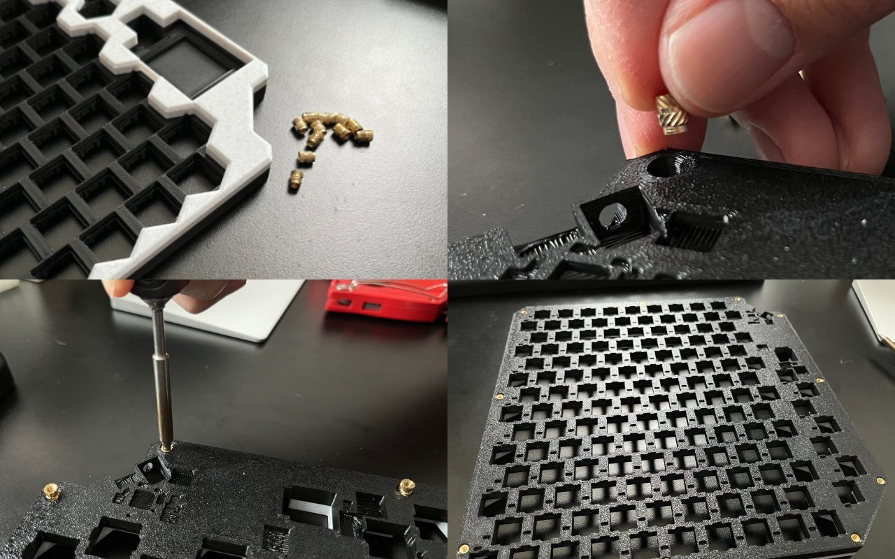
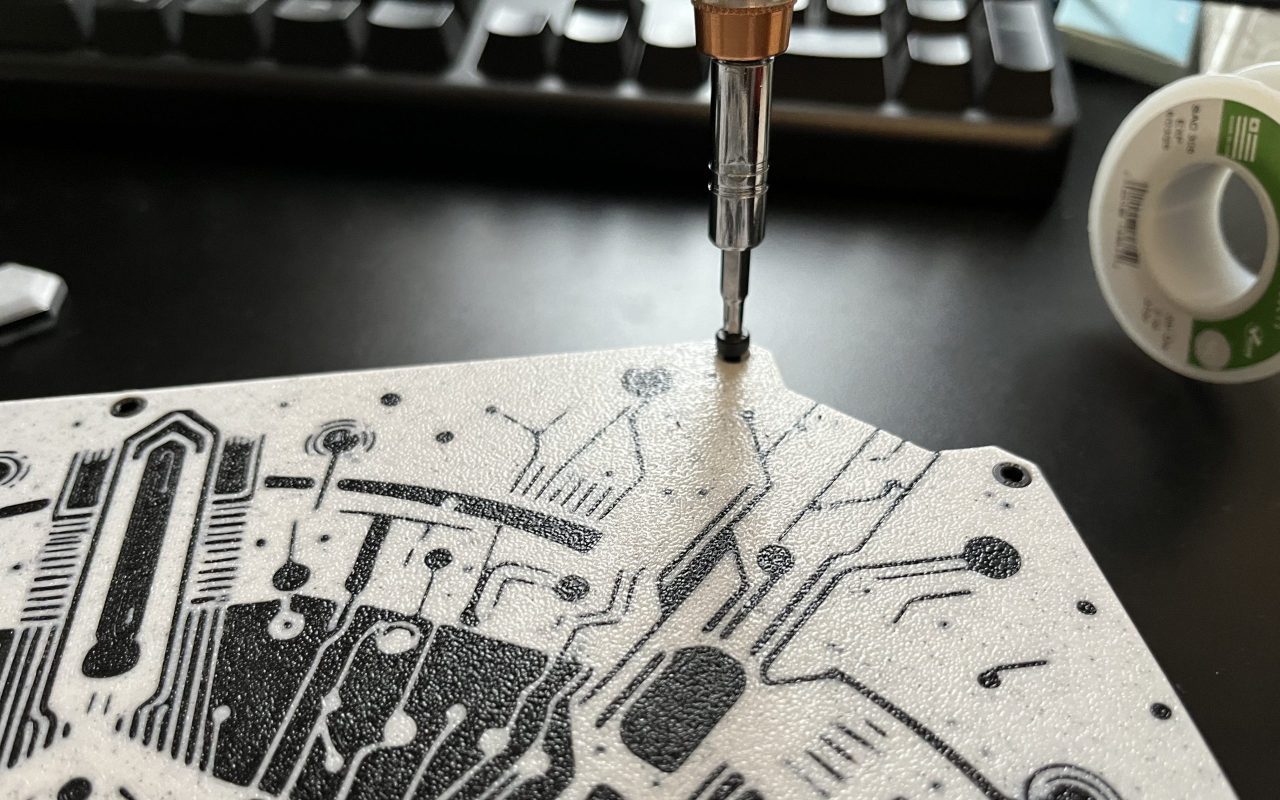
Take the 11 brass inserts and place them skinny side down into the holes on the back of the frame. Use your soldering iron to press them in. Make sure they go in just past flush. You will experience regret among other unpleasant emotions if you solder the switches in before this step. (don’t ask me how I know)
Step 2:
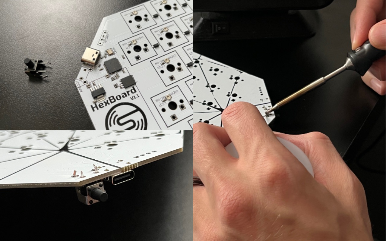
Take the right-angle tact switch and solder it in place next to the USB port.
Step 3:
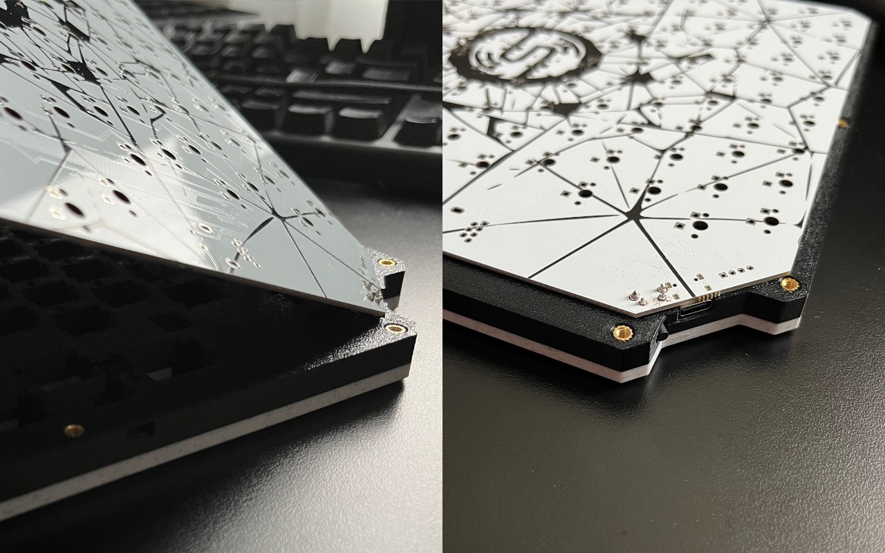
Insert the circuit board into the frame at an angle with the programming button first.
Step 4:
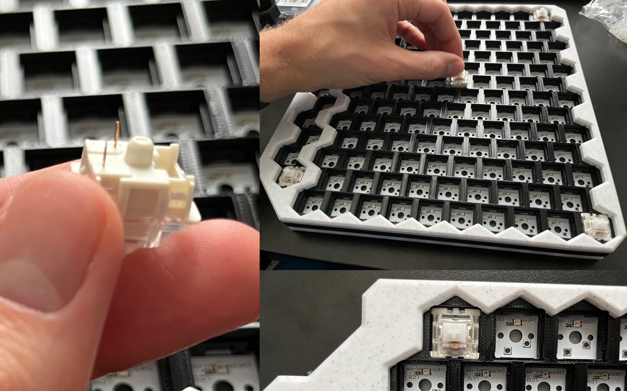
Take 5 switches and place them in the corners and the center making sure to check that the pins are unbent and they are oriented correctly to allow the LED to shine through.
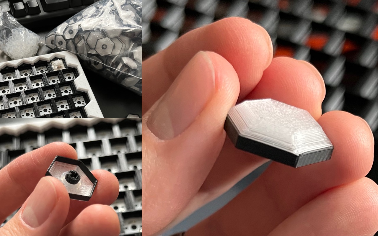
Step 5:
Take your keycaps and o-rings. Place one o-ring on the stem of the keycap and firmly press it onto a switch. Repeat until you have capped all 5 switches. Make sure the seams on the keycaps are all facing downward or you’ll have an inconsistent look. I include a handful of spare keycaps, so pick the ones you think looks best. (forgot to take a picture of the caps on the keys, but God gave you an imagination, so I’m sure you’ll manage)
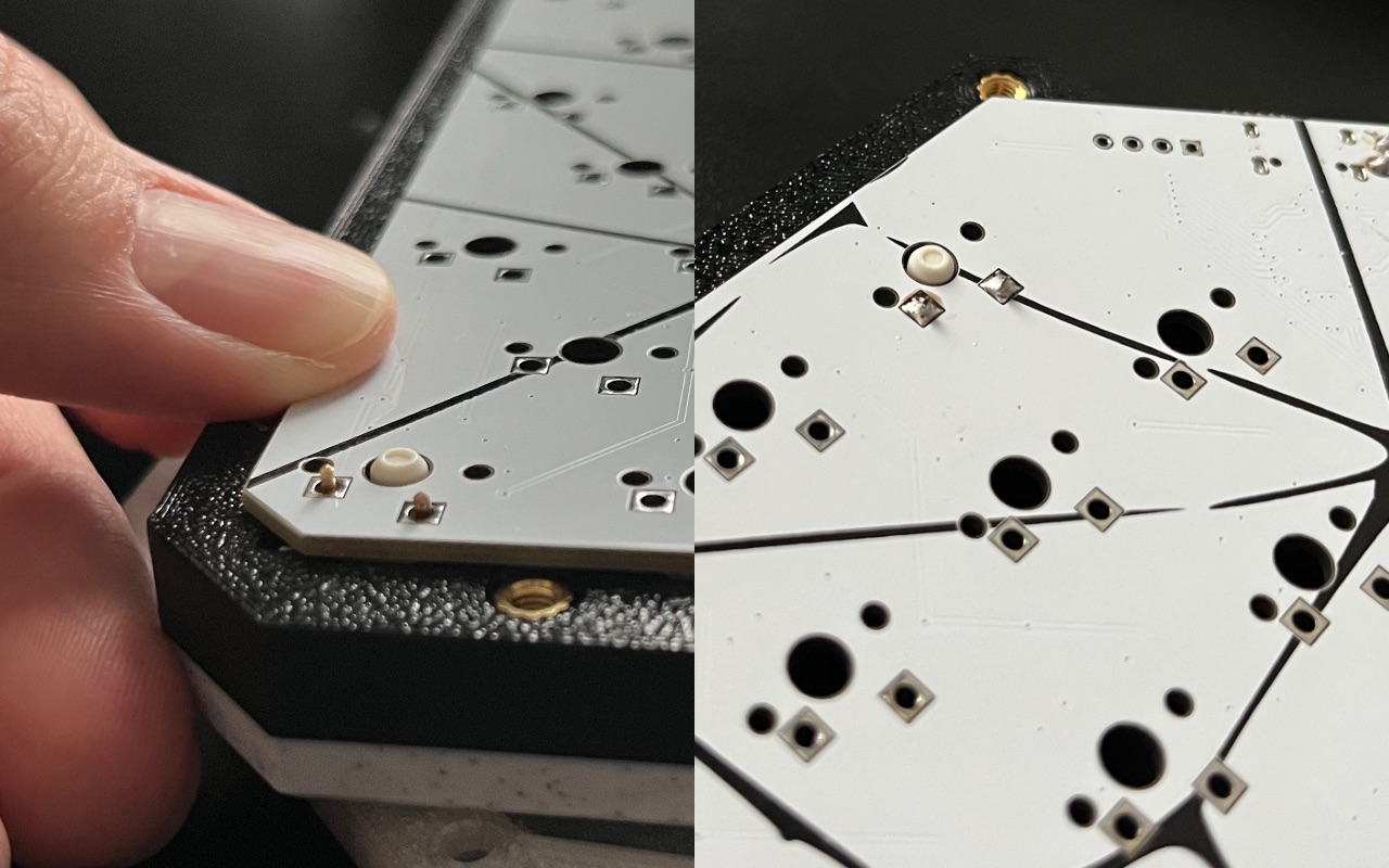
Step 6:
Flip over your board. Press firmly next to each switch as you solder the legs into place. This is important because it will center and anchor the board into place for the future switches. Don’t solder the switches in until the center stem pushes out like the picture and don’t let off pressure until the solder joint cools off. If you bent either of the legs pressing the switch in place, use the clips on the top and bottom of the switch with some force to remove it.
This step is the trickiest part. Take your time to get it right the first time as desoldering runs the risk of ripping up traces and making your life difficult. Perhaps practice soldering with a tutorial if you’re not confident. That said, it’s fairly simple. Take your time and you’ll be just fine.
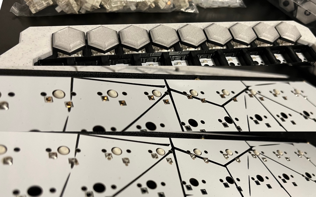
Step 7:
Time to press in all the rest of the buttons. Follow the same procedure as above, but for the rest of the keys. I’d recommend starting a row at a time making sure you don’t solder until you check the legs all poke through the board. Again, pressure on the board while soldering promotes height consistency.
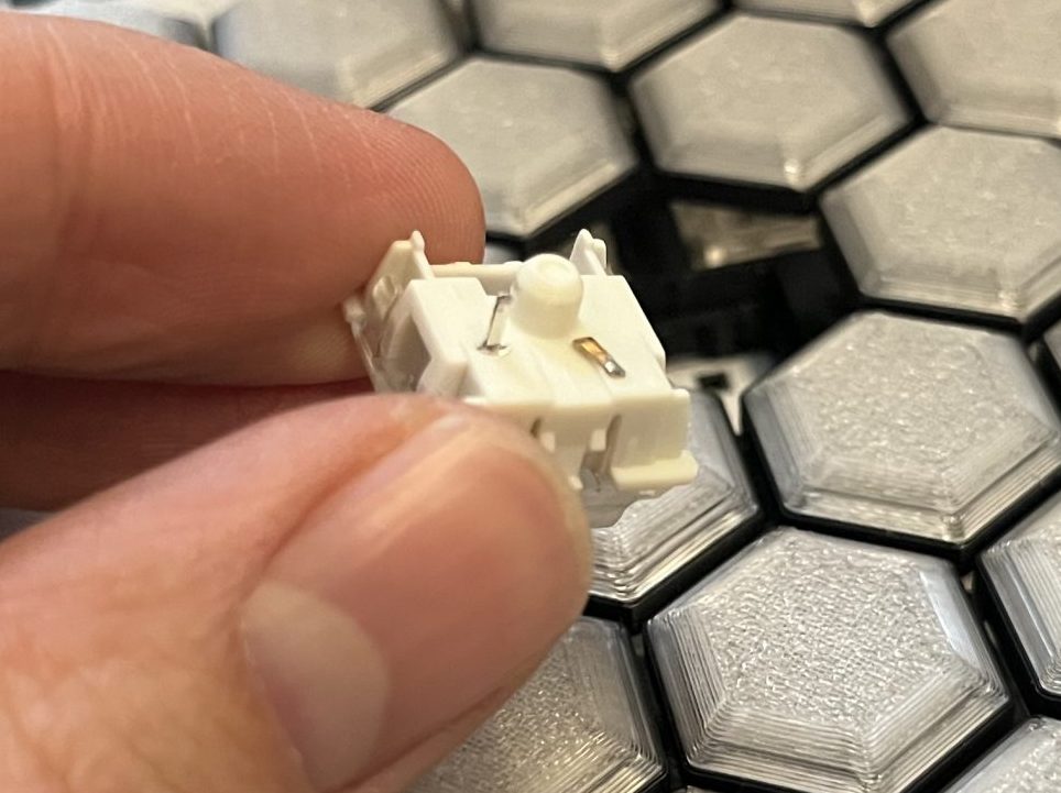
Oopsie! This switch was bent when inserting and just got worse when I pressed it in. Fortunately, I was able to successfully desolder the leg that I already soldered, but it would have been better if I had checked before soldering.
Step 8:
Now that the switches are all installed, request a high-five from the nearest person to you. (yourself if over a quarter mile (.4 kilometers) from another human) You’ve made it through the most tedious part.
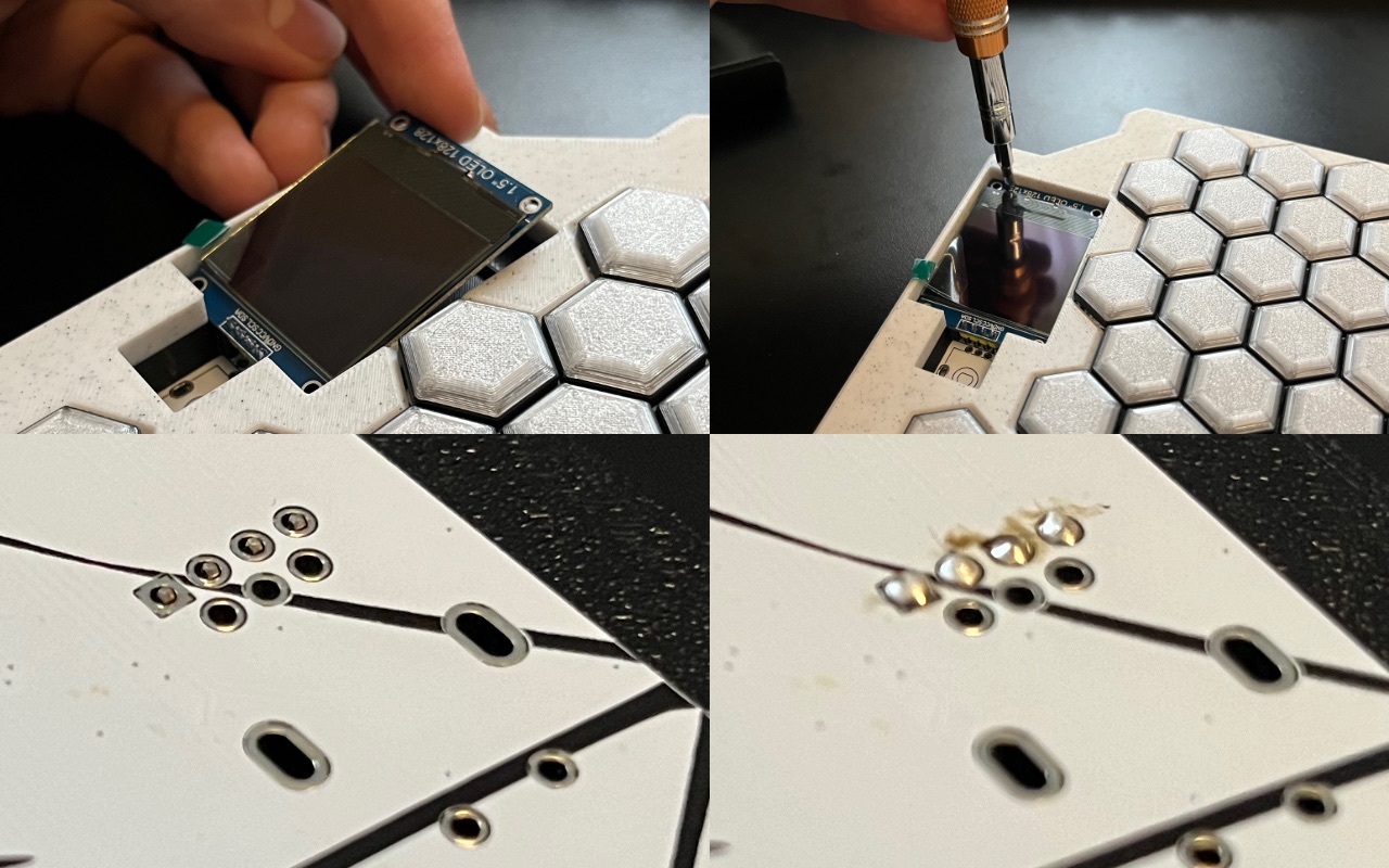
Next, set the display in place at a slight angle to get the pins lined up with the holes. Then use a tool to press on the top and bottom edges of the circuit board (NOT the display itself) to get it locked in place. The four pins should barely make it through the board. Solder those in place.
Step 9:
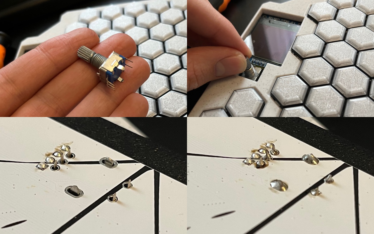
Take the encoder and straighten out the pins. Set it in place below the screen and hold it in place while you flip over the HexBoard. Solder in the pins while making sure it’s lined up. You will need to crank up the heat on your soldering iron to get the large mounting tabs soldered on.
Step 10:
Screw in the 11 bolts to attach the back plate to the frame. The bolts should be flush to the surface. Don’t use too much force or you risk pulling out the heat set inserts. Shouldn’t take much force to screw in anyways.
Step 11:
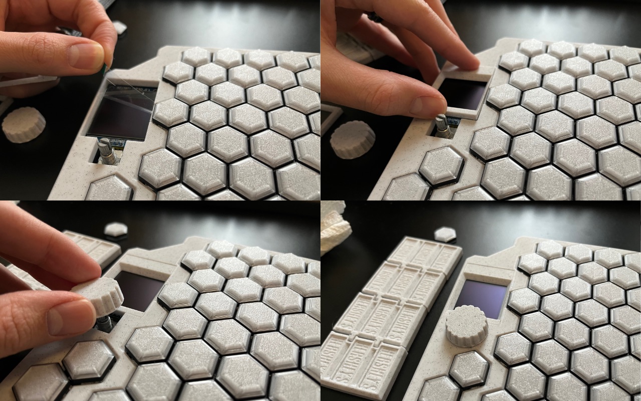
Peel the protective film off the screen. Press the screen bezel in place followed by the encoder knob. That’s it! You’re done!
Congratulations, now go touch some grass and breathe a little fresh air, you’ve been inside for far too long.